ELSACALC - ELSA construction calculator
I have entered some default values and calculated the results for you. You can change any of the values and then click the
'calculate' buttons to recalculate the results. Have fun designing the most efficient
ELSA machine you can and remember to keep an eye on the compression ratio since sealing
becomes more of a problem as the pressure increases.
Prajña.
Last updated on 30/08/2006 at 08:15hrs
First we need to decide to what height we will pump the water:
(meters)
Then choose the internal diameter of our header tube:
(centimeters)
From that we can calculate the head of water in the header tube by simply calculating its volume:
So the volume of water in our header tube is litres
[π r2 * height]
Next we need to decide how deep our pumping tube will be:
(meters)
Then choose its internal diameter:
(centimeters)
and the height of our shuttle:
(centimeters)
Now we have all the information we need to calculate the rest:
We know that the shuttle volume is litres
[π r2 * height]
Therefore our shuttle will have to weigh at least kg in order to sink
since it displaces that weight of water
We know that the combined weight of our head and our shuttle is kg
by simply adding the two values
So we will need to displace litres of water to lift the head and the shuttle. We will call this the displacement volume.
And we can pump litres on each stroke
[volume (i.e. π r2 * height) of the pumping tube - displacement volume]
We know that the pressure at m depth is times
the pressure at water level.
[(height in meters / 10) + 1]
So we will have to compress times our displacement volume into the shuttle
i.e. litres
[2 * max pressure * displacement volume]
So the pressure inside our shuttle will be bar (remember that most pressure
gauges are set to read 0 at sealevel.)
[(total compressed volume / shuttle volume) - 1]
To compress 1 litre of air to half its volume we need to double the weight on top of it.
We already know the pressure acting at sealevel. It is approximately 14.5 psi or 1.02 kg/cm2 due to the weight of the atmosphere.
It follows that 1 litre of air in a tube 1cm by 1cm by 10m could be compressed to 5m (or twice its pressure) by adding a weight of approximately 1kg
Taking the height of our head as the height of the cylinder of air to compress we can calculate the weight that must be added to the top of that cylinder in order to compress it by our required ratio.
litres divided by m will give us an area of cm2
So we need a weight of kg times our compression ratio of
:1 to recompress the shuttle.
i.e. kg
Subtracting that from the total volume of water pumped gives us an excess of litres stored at m after we have recompressed the shuttle.
That might sound like a lot but it represents a stored potential energy of kilojoules
which is approximately
So we are using quite a big machine to produce a relatively small energy output. Having said that, a hydroelectric power station is a huge machine and this is tiny by comparison. Free energy is free after all and it is rather a treat to see something pump water up hill with a net gain of energy. Remember also that these are the results for just one cycle of the machine. We assume it will keep running (albeit slowly due to fluid dynamics) and produce this excess of energy for each stroke.
We might also be interested in the efficiency of this system, which we can calculate
by dividing the total water pumped by that consumed in recompressing the
shuttle. This gives us an efficiency of
We can increase the efficiency by compressing the air via a lever system. That means we can use considerably less water to compress the air.
Remember that these calculations are based on an ideal model. We do not take into account the friction between the shuttle and the walls of the pumping cylinder, for instance, and we assume that our compression system is 100% efficient (which, to my knowledge, none are). If you were buliding this machine for real then you would also have to factor in that the internal capacity of the shuttle is smaller than its displacement (so the compression would have to be higher). There will be inefficiencies in the valve switching and any competent engineer will tell you that there are inefficiencies using a port system too.
Still, when everything is taken into account, it is difficult not to find this concept completely marvelous.
Many grateful thanks to 'tbird' on overunity.com for picking me up on silly errors in my calculations - particularly with reference to pressure, which I found very confusing. Also to Stefan 'hartiberlin' Hartmann for hosting overunity.com and Andi (ooandioo) for posting the message that got us all interested in ELSA again (and enthusiastic to prove or disprove the concept). Not to mention the others who have contributed to the discussion.
Lastly, or I should say 'most of all', to Mr John D. Herring Sr. for so freely publishing his idea on theverylastpageoftheinternet in the first place.

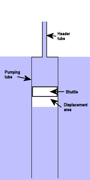
General layout

Compression cycle
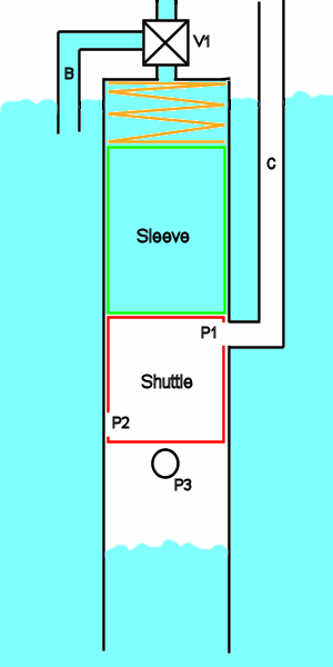
When the shuttle (red) reaches the top of the pumping tube it lifts the sleeve (green) and compresses the spring (orange).
The sleeve normally blocks the compression port (marked 'P1') and the displacement port (marked 'P3'). When the shuttle lifts the sleeve air flows from the compression tube (marked 'C') into the shuttle and air drains from the displacement area (being replaced by water from below).
Whilst that is happening valve 'V1' is closed. This locks the shuttle in place by hydraulic pressure in the space above the shuttle.
Once the shuttle has been filled valve 'V1' is set to allow water to flow into the top of the pumping cylinder via the backfill tube (marked 'B') which releases the shuttle. As the shuttle descends, the sleeve returns to its normal position covering ports 'P1' and 'P3'.

Decompression cycle
When the shuttle reaches the bottom port P2 is aligned with the transfer pipe and air flows from the shuttle into the displacement area. Whilst this is happening valve 'V1' (on the previous picture) is closed so that the shuttle is again locked in place.
Once the pressure has equalised between the shuttle and the decompression area valve 'V1' is set to allow water to flow up the header pipe and the shuttle rises to the top of the pumping cylinder for the cycle to repeat.
Valve 'V1' should be operated by an actuator connected to a sensor on the compression tube. A drop in pressure will indicate that the shuttle has opened port 'P1'. An increase in pressure will indicate that the shuttle is fully compressed.
There also need to be sensors at the bottom of the pumping tube to detect the arrival of the shuttle and the equalisation of pressure.
Probably a single pressure sensor could be used in the shuttle and its signal interpreted by a logic system to control the actuator.